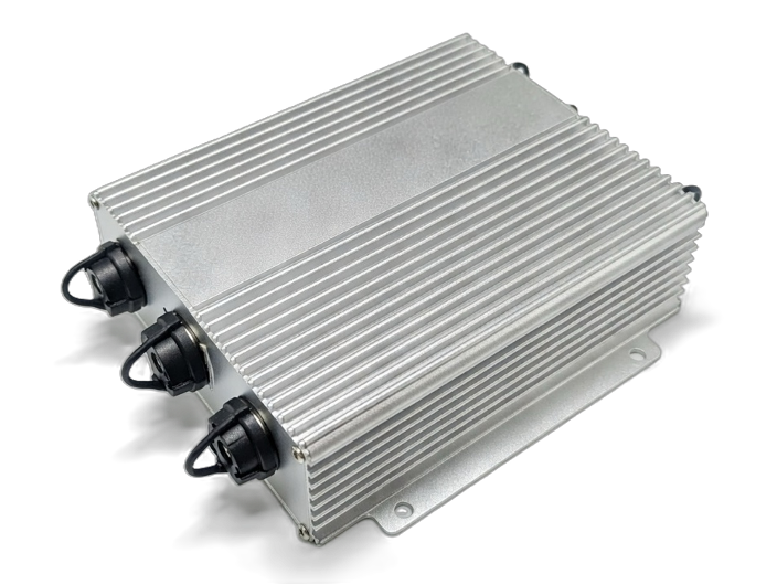
Controller
Tram Wiper Controller
Built for rail transit wiper systems with stable control output and reliable operation in demanding environments.
Parameters
| System Type | Tram Wiper Control Unit |
|---|---|
| Control Channels | Multi-channel |
| Mounting | Panel / cabinet mount |
| Application | Rail transit and tram wiper systems |
Controller function
Key Functions
| Controller function | Operation stages |
|
|---|---|---|
| Wiper motor | Working voltage |
|
| Wiper motor | No-load current |
|
| Wiper motor | Loaded current |
|
| Washer pump | Working voltage |
|
Optional functions
- A communication cable (CH4) is connecting both controllers on each cab for the operation of trailing cab wiper. The wiper of trailing cab will work in a constant speed (25±3 RPM) regardless of the speed of the wiper of active cab.
- When two LRVs are operated with coupled position, both CH4 and CH7 connected with extension cables.
- The wiper located in the leading cab is turned on, the wipers located in the middle of the connected LRVs will be deactivated and the wiper located in the rear cab of trailing LRV will be operated in a constant speed (25±3 RPM).
- Mating connectors shall be available at coupling locations, so controllers between 2 LRVs will be connected for communication.
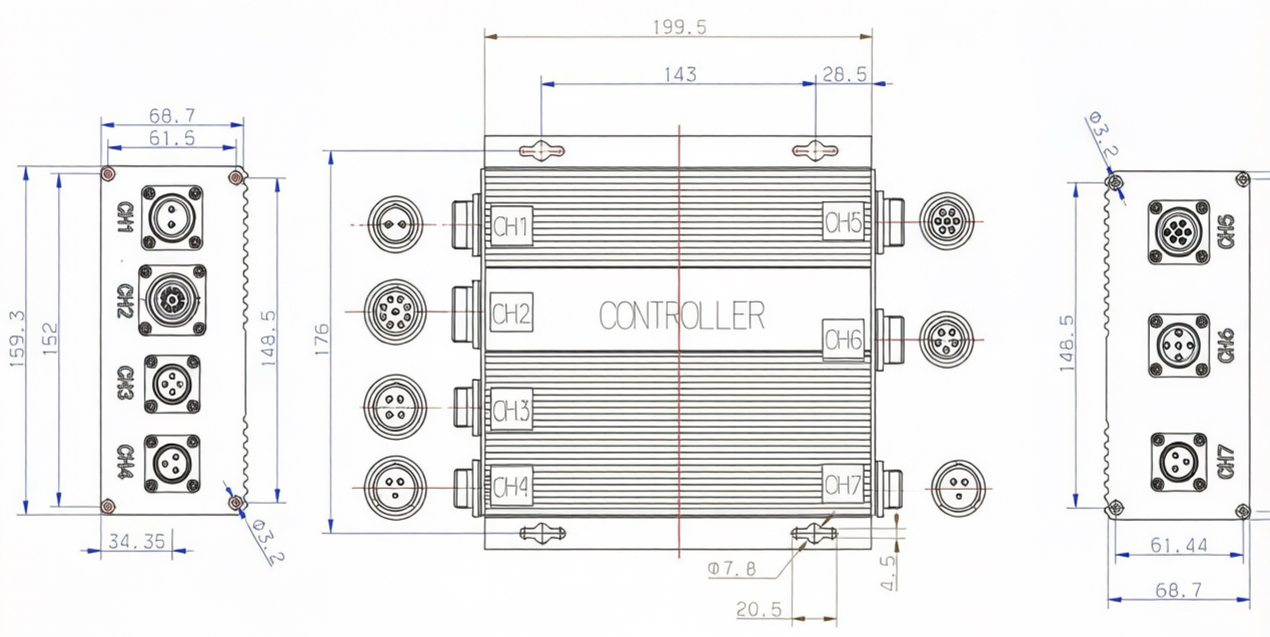
Dimension
Wiring
Wiring Preview
Power input (CH1)
- DC24V+
- DC24V-
Functional switch (CH2)
- No.1: (-)
- No.2: Long time interval (17±2s)
- No.3: Short time interval (6±2s)
- Empty: Stop (Parking)
- No.4: Slow
- No.5: Medium
- No.6: Fast
- No.7: Spray
- No.8: Washer liquid shortage signal
- No.9: Washer liquid full signal
Water pump & liquid level sensor (CH5)
- No.1: Pump +
- No.2: Pump -
- No.3: Washer liquid full signal
- No.4: Washer liquid shortage signal
- No.5: (-)
DC24V motor (CH6)
- No.1: Motor winding line U
- No.2: Motor winding line V
- No.3: Motor winding line W
- No.4: Signal line
- No.5: Signal line
Alarm / HCR input (CH3)
- No.2: Washer liquid insufficient alarm
- No.1: Washer liquid insufficient alarm
- No.4: (+)HCR input
RS485 communication (CH4 / CH7)
- CH4 No.2: (-) RS485
- CH4 No.1: (+) RS485
- CH7 No.2: (-) RS485
- CH7 No.1: (+) RS485
Note
- When washer liquid shortage, No.1 and No.2 are always closed.
- In normal condition, No.1 and No.2 are always open.
Product Image